On my trials and tribulations with 3D modelling software

Best Selling RPGs - Available Now @ DriveThruRPG.com

Nobby-W

Not an axe murderer
Joined
Oct 7, 2018
Messages
7,070
Reaction score
16,007
My adventures with 3D modelling, part 1.

So, I spent a frustratingly large amount of time in attempts to troubleshoot Blender's array modifier facility, but eventually figured out how to array items around a central axis. As such, my attempts over the past couple of days to teach myself how to use it by drawing a space station are showing a small modicum of progress. It's still a bunch of primitives without any greebling or textures, but it's a start.

I decided to start with Blender because it's (a) free, (b) widely used and (c) by all accounts a fairly capable system. It used to get a lot of shade over its gnarly UX but not for its lack of capability with the exception of (from what I can tell) Maya snobs. One of the strikes against Sketchup was its dependence on third-party plugins for functionality. For example, it doesn't really have a proper subdivision operator out of the box. It might have been alright but I didn't fancy juggling a plugin-fest on something I was trying to learn.

A little bit of background

I've decided to embark on doing some intrinsically 3-dimensional items in 3D in order to lubricate the design process. When I can get stuff down on paper or at least into a file then this process engages bits of my brain that would otherwise lie idle, and improves the quality of the creative work and ability to delve into detail. You can see some work on a city and starport town in another of the postings on this forum.

The first 3D project is Freeside Station, a sort of free city in space whose original owners were dissolved by historical events and replaced by the current ruling factions. This is, as one might expect, a wretched hive of scum and villainy in which our intrepid PCs will find themselves right at home. It has the usual suspects for such a location - NPCs, encounters, politics and factions, interesting locations and so forth. It's one of a few 'home ports' I'm doing for the setting, which are designed to be bases of operations for characters, with domestic politics to make things interesting.

My learnings so far
  • I've spent more time trying to troubleshoot why the array function was applying spurious transforms to the clones it was producing. I think I've got that figured out now. The original objects I was cloning in the array had transforms in their definitions without being applied to the object itself to create a definition of a transformed object rather than a primitive object with a transformation. This means that the array was re-applying the transformation to each clone, producing very strange results. Most of yesterday and today (including some bits of today when I should have been doing other things) was spent trying to figure out how to stop it from doing this.
  • The drawing isn't to scale, although I'll do another one that is once I've figured out how to do stuff on this.
  • It took a bit of frigging to get lathing to work for the rings, but it did eventually work.
  • Learning how to use the 3D cursor is a key skill.
  • Empty objects are quite useful
  • It's still running OK on my T430 with built-in graphics. I think the capabilities of the Intel mobo chipsets are somewhat underrated.
I think there's still a lot of work in getting to understand Blender - 3D modelling software is quite complex. It's also got a scripting facility so I may try it for rendering starmaps at some point. There is also a utility called Blend2Web that can generate WebGL renderings. I haven't tried either of these yet and probably won't for a while.

This is what I came up with after a few hours tinkering and a lot more time googling around in an attempt to figure out how to get the spurious transformations out of my arrays. It's nowhere close to finished art, but it is a first step.

SpaceStation1.jpg
 
Last edited:
OMG, I am trying so hard not to Kool -Aid man this thread right now, you ae speaking my language here... Space stations and 3D!

I'm new to blender too. its a fustrating program to learn if you have any other 3d backround... but not so bad if you are a virgin modeller. It's frickin powerful though. It honestly does everything as good as, or almost as good as but better with plugins, than the other specialized programs out there.
I find the hardest part of learning blender is the concentration fatigue. I work with it in spurts instead of long sessions because so much of it is not intuitive coming from other programs.
Most folks throwing shade on Blender seem to be dissing it for its UX rather than lack of features. Either that or they're just partisan mine's-better-than-yours Maya snobs.

I remember stalking your deviantart page and seeing some of the stuff you did once. What did you use to make those?
 
Last edited:
Most folks throwing shade on Blender seem to be dissing it for its UX rather than lack of features. Either that or they're just partisan mine's-better-than-yours Maya snobs.

I remember stalking your deviantart page and seeing some of the stuff you did once. What did you use to make those?
Newtek lightwave and photoshop.
Lightwave is rather primitive now though, hence my foray into blender.
 
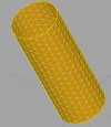
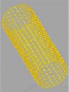
And here's a programmatically generated geodetic cylinder. I spent an evening tinkering with CADQuery - a 3D modelling engine with a scripting API (see below) and got this to generate a geodetic cylinder as a prototype for a space station module. Script attached below - note that CADQuery needs Miniconda to install - I spent nearly as much time faffing about with the installer as I spent figuring out how to do this..

Geodetic.jpg


Python:
# === Geodesic.py ====================================================

from math import sin, cos, radians, pi
import cadquery as cq

radius = 60000.0
height = 320000.0

steps = 12
step = radians (360.0/steps/2)

sin30 = sin (radians (30))
cos30 = cos (radians (30))
sin60 = sin (radians (60))
cos60 = cos (radians (60))

ystep = radius / (steps/pi * sin60)


def geodetic1 (yy, clip):

    for theta in [radians (360.0/steps) * xx for xx in range(steps)]:

        origin1 = (sin (theta) * radius, yy, cos (theta) * radius)
        xdir1 = (cos (theta + step) * radius, 0.0, sin (theta + step) * radius * -1.0)
        norm1 = (sin (theta + step/2.0), 0.0, cos (theta + step/2.0))

        origin2 = (sin (theta + step) * radius, yy, cos (theta + step) * radius)
        xdir2 = (cos (theta + step * 2) * radius, 0.0, sin (theta + step * 2) * radius * -1.0)
        norm2 = (sin (theta + step * 1.5), 0.0, cos (theta + step * 1.5))

        if clip == -1:
            (x1, y1) = (0, step/sin60 * 0.5 * radius)
            (x2, y2) = (step * radius, 0)
            (x3, y3) = (0, 0)
            (x4, y4) = (step * radius, step * radius / sin60) 
        elif clip == 1:
            (x1, y1) = (0, step/sin60 * 0.5 * radius)
            (x2, y2) = (step * radius, 0)
            (x3, y3) = (0, -step/sin60 * 0.5 * radius)
            (x4, y4) = (step * radius, step/sin60 * 0.5 * radius) 
        else:
            (x1, y1) = (0, step/sin60 * 0.5 * radius)
            (x2, y2) = (step * radius, 0)
            (x3, y3) = (0, -step/sin60 * 0.5 * radius)
            (x4, y4) = (step * radius, step * radius / sin60)         

        if clip == -1:
            (xp1, yp1) = (step * radius, step/sin60 * 0.5 * radius)
            (xp2, yp2) = (0, 0)
            (xp3, yp3) = (step * radius, 0)
            (xp4, yp4) = (0, step * radius / sin60)   
        elif clip == 1:
            (xp1, yp1) = (step * radius, step/sin60 * 0.5 * radius)
            (xp2, yp2) = (0, 0)
            (xp3, yp3) = (step * radius, -step/sin60 * 0.5 * radius)
            (xp4, yp4) = (0, step/sin60 * 0.5 * radius)
        else:
            (xp1, yp1) = (step * radius, step/sin60 * 0.5 * radius)
            (xp2, yp2) = (0, 0)
            (xp3, yp3) = (step * radius, -step/sin60 * 0.5 * radius)
            (xp4, yp4) = (0, step * radius / sin60)

        plane1 = cq.Workplane (cq.Plane (origin1, xDir=xdir1, normal=norm1))

        obj1 = \
            plane1.moveTo (x1, y1) \
                .lineTo (x2, y2) \
                .lineTo (x3, y3) \
                .close() \
                .extrude (1000)

        obj2 = \
            plane1.moveTo (x2, y2) \
                .lineTo (x1, y1) \
                .lineTo (x4, y4) \
                .close() \
                .extrude (1000)

        plane2 = cq.Workplane (cq.Plane (origin2, xDir=xdir2, normal=norm2))
  
        obj3 = \
            plane2.moveTo (xp1, yp1) \
                .lineTo (xp2, yp2) \
                .lineTo (xp3, yp3) \
                .close() \
                .extrude (1000)
  
        obj4 = \
            plane2.moveTo (xp2, yp2) \
                .lineTo (xp1, yp1) \
                .lineTo (xp4, yp4) \
                .close() \
                .extrude (1000)

        show_object (obj1)
        show_object (obj2)
        show_object (obj3)
        show_object (obj4)   


geodetic1 (0, -1)
for row in range (1, 17):
    geodetic1 (ystep * row, 0)
  
geodetic1 (ystep * 17, 1)
 
Last edited:
Oooh. Constructive solid geometry. Shiny!

CSG3.jpgCSG2.jpg

Python:
# === Geodesic.py ====================================================

from math import sin, cos, radians, pi, sqrt
import cadquery as cq

master_radius = 60000.0
master_height = 320000.0
master_thick = 200
master_extrude = -2000

steps = 12
step = radians (360.0/steps/2)

sin30 = sin (radians (30))
cos30 = cos (radians (30))
sin60 = sin (radians (60))
cos60 = cos (radians (60))

ystep = master_radius / (steps/pi * sin60)
master_list = []


def geodetic1 (yy, radius, clip, thick, extrude, display_list):

    for theta in [radians (360.0/steps) * xx for xx in range(steps)]:

        origin1 = (sin (theta) * radius, yy, cos (theta) * radius)
        xdir05 = (cos (theta) * radius, 0.0, sin (theta) * radius * -1.0)
        xdir1 = (cos (theta + step) * radius, 0.0, sin (theta + step) * radius * -1.0)
        norm05 = (sin (theta), 0.0, cos (theta))
        norm1 = (sin (theta + step/2.0), 0.0, cos (theta + step/2.0))

        origin2 = (sin (theta + step) * radius, yy, cos (theta + step) * radius)
        xdir15 = (cos (theta + step) * radius, 0.0, sin (theta + step) * radius * -1.0)
        xdir2 = (cos (theta + step * 2) * radius, 0.0, sin (theta + step * 2) * radius * -1.0)
        norm15 = (sin (theta + step), 0.0, cos (theta + step))
        norm2 = (sin (theta + step * 1.5), 0.0, cos (theta + step * 1.5))

        (x1, y1) = (0, step/sin60 * 0.5 * radius)
        (x2, y2) = (step * radius, 0)
        (xp1, yp1) = (step * radius, step/sin60 * 0.5 * radius)
        (xp2, yp2) = (0, 0)

        if clip == -1:
            (x3, y3) = (0, 0)
            (xp3, yp3) = (step * radius, 0)
        else:
            (x3, y3) = (0, -step/sin60 * 0.5 * radius)
            (xp3, yp3) = (step * radius, -step/sin60 * 0.5 * radius)

        if clip == 1:
            (x4, y4) = (step * radius, step/sin60 * 0.5 * radius)
            (xp4, yp4) = (0, step/sin60 * 0.5 * radius)
        else:
            (x4, y4) = (step * radius, step * radius / sin60)
            (xp4, yp4) = (0, step * radius / sin60)

        plane05 = cq.Workplane (cq.Plane (origin1, xDir=xdir05, normal=norm05))
        plane1 = cq.Workplane (cq.Plane (origin1, xDir=xdir1, normal=norm1))

        part11 = prism (plane1, x1, y1, x2, y2, thick, extrude)
        part12 = prism (plane1, x2, y2, x3, y3, thick, extrude)
        part13 = prism (plane05, x3, y3, x1, y1, thick, extrude)
        display_list.append (part11)
        display_list.append (part12)
        display_list.append (part13)
        if clip == 1:
            part15 = prism (plane1, x1, y1, x4, y4, thick, extrude)
            display_list.append (part15)         

        plane15 = cq.Workplane (cq.Plane (origin2, xDir=xdir15, normal=norm15))
        plane2 = cq.Workplane (cq.Plane (origin2, xDir=xdir2, normal=norm2))
      
        part21 = prism (plane2, xp1, yp1, xp2, yp2, thick, extrude)
        part22 = prism (plane2, xp2, yp2, xp3, yp3, thick, extrude)
        part24 = prism (plane15, xp4, yp4, xp2, yp2, thick, extrude)
        display_list.append (part21)
        display_list.append (part22)
        display_list.append (part24)
        if clip == 1:
            part25 = prism (plane2, xp1, yp1, xp4, yp4, thick, extrude)
            display_list.append (part25)


def prism (plane, x1, y1, x2, y2, thick, high):
    (xx, yy) = (x2-x1, y2-y1)
    hyp = sqrt (xx**2 + yy**2)
    (normx, normy) = ((-yy / hyp) * (thick/2), (xx / hyp) * (thick/2))
    obj = \
        plane.moveTo (x1 + normx, y1 + normy) \
            .lineTo (x1 - normx, y1 - normy) \
            .lineTo (x2 - normx, y2 - normy) \
            .lineTo (x2 + normx, y2 + normy) \
            .close() \
            .extrude (high)
    return obj


def gcylinder (radius, rows, display_list):
    geodetic1 (0, radius, -1, master_thick, master_extrude, display_list)
    for row in range (1, rows):
        geodetic1 (ystep * row, radius, 0, master_thick, master_extrude, display_list)
  
    geodetic1 (ystep * rows, radius, 1, master_thick, master_extrude, display_list)
  

gcylinder (master_radius, 2, master_list)


pp = cq.Workplane ('XY')
for item in master_list:
    pp.add(item)
tri = pp.union(pp)
show_object (tri)
 
Last edited:
Most annoying. Trying to make up a cylinder to intersect the geodetic structure with is causing the machine to go into the weeds. Not sure if this is a bug or I've just asked the machine to do something computationally intractable. It's a nice experiment but comfortably into the realms of too f-ing slow.
 
Last edited:
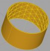
Well, figured out the problem (I think), and we now have the geodetic grid clipped to a cylinder and merged with a cylindrical wall. It takes a while to generate the model, though. It's got a CPU core pegged and it's using a GB or so of RAM, so it's got something going on. Unfortunately it's getting too slow now. Not sure why. The underlying library is in C++, so I could blow the cobwebs out of that and try building something natively against it, but the visualiser I'm using here is tied to Python.

CSG4.jpg

Python:
# === Geodesic.py ====================================================

from math import sin, cos, radians, pi, sqrt
import cadquery as cq

master_radius = 60000.0
master_rows = 3
master_thick = 200
master_extrude = 2000
master_wall = 200

steps = 12
step = radians (360.0/steps/2)

sin30 = sin (radians (30))
cos30 = cos (radians (30))
sin60 = sin (radians (60))
cos60 = cos (radians (60))

ystep = master_radius / (steps/pi * sin60)
master_list = []
master_height = ystep * (master_rows + 0.5)
print (master_height)


def geodetic1 (yy, radius, clip, thick, extrude, display_list):

    for theta in [radians (360.0/steps) * xx for xx in range(steps)]:

        origin1 = (sin (theta) * radius, yy, cos (theta) * radius)
        xdir05 = (cos (theta) * radius, 0.0, sin (theta) * radius * -1.0)
        xdir1 = (cos (theta + step) * radius, 0.0, sin (theta + step) * radius * -1.0)
        norm05 = (sin (theta), 0.0, cos (theta))
        norm1 = (sin (theta + step/2.0), 0.0, cos (theta + step/2.0))

        origin2 = (sin (theta + step) * radius, yy, cos (theta + step) * radius)
        xdir15 = (cos (theta + step) * radius, 0.0, sin (theta + step) * radius * -1.0)
        xdir2 = (cos (theta + step * 2) * radius, 0.0, sin (theta + step * 2) * radius * -1.0)
        norm15 = (sin (theta + step), 0.0, cos (theta + step))
        norm2 = (sin (theta + step * 1.5), 0.0, cos (theta + step * 1.5))

        (x1, y1) = (0, step/sin60 * 0.5 * radius)
        (x2, y2) = (step * radius, 0)
        (xp1, yp1) = (step * radius, step/sin60 * 0.5 * radius)
        (xp2, yp2) = (0, 0)

        if clip == -1:
            (x3, y3) = (0, 0)
            (xp3, yp3) = (step * radius, 0)
        else:
            (x3, y3) = (0, -step/sin60 * 0.5 * radius)
            (xp3, yp3) = (step * radius, -step/sin60 * 0.5 * radius)

        if clip == 1:
            (x4, y4) = (step * radius, step/sin60 * 0.5 * radius)
            (xp4, yp4) = (0, step/sin60 * 0.5 * radius)
        else:
            (x4, y4) = (step * radius, step * radius / sin60)
            (xp4, yp4) = (0, step * radius / sin60)

        plane05 = cq.Workplane (cq.Plane (origin1, xDir=xdir05, normal=norm05))
        plane1 = cq.Workplane (cq.Plane (origin1, xDir=xdir1, normal=norm1))

        part11 = prism (plane1, x1, y1, x2, y2, thick, extrude)
        part12 = prism (plane1, x2, y2, x3, y3, thick, extrude)
        part13 = prism (plane05, x3, y3, x1, y1, thick, extrude)
        display_list.append (part11)
        display_list.append (part12)
        display_list.append (part13)
        if clip == 1:
            part15 = prism (plane1, x1, y1, x4, y4, thick, extrude)
            display_list.append (part15)       

        plane15 = cq.Workplane (cq.Plane (origin2, xDir=xdir15, normal=norm15))
        plane2 = cq.Workplane (cq.Plane (origin2, xDir=xdir2, normal=norm2))
    
        part21 = prism (plane2, xp1, yp1, xp2, yp2, thick, extrude)
        part22 = prism (plane2, xp2, yp2, xp3, yp3, thick, extrude)
        part24 = prism (plane15, xp4, yp4, xp2, yp2, thick, extrude)
        display_list.append (part21)
        display_list.append (part22)
        display_list.append (part24)
        if clip == 1:
            part25 = prism (plane2, xp1, yp1, xp4, yp4, thick, extrude)
            display_list.append (part25)


def prism (plane, x1, y1, x2, y2, thick, high):
    (xx, yy) = (x2-x1, y2-y1)
    hyp = sqrt (xx**2 + yy**2)
    (normx, normy) = ((-yy / hyp) * (thick/2), (xx / hyp) * (thick/2))
    obj = \
        plane.moveTo (x1 + normx, y1 + normy) \
            .lineTo (x1 - normx, y1 - normy) \
            .lineTo (x2 - normx, y2 - normy) \
            .lineTo (x2 + normx, y2 + normy) \
            .close() \
            .extrude (high)
    return obj


def gcylinder (radius, rows, display_list, extrude):
    geodetic1 (0, radius, -1, master_thick, extrude * -1, display_list)
    for row in range (1, rows):
        geodetic1 (ystep * row, radius, 0, master_thick, extrude * -1, display_list)

    geodetic1 (ystep * rows, radius, 1, master_thick, extrude * -1, display_list)


gcylinder (master_radius + master_extrude, master_rows, master_list, master_extrude * 3)


p1 = cq.Workplane ('XZ')
inner1 = p1.circle(master_radius - master_extrude).extrude (-master_height - master_thick - 1000)
inner2 = p1.circle(master_radius - master_extrude).extrude (1000)
inner = inner1.union (inner2)

p2 = cq.Workplane ('XZ')
inner1 = p2.circle(master_radius - master_wall).extrude (-master_height - master_thick - 1000)
inner2 = p2.circle(master_radius - master_wall).extrude (1000)
inner3 = inner1.union (inner2)

p3 = cq.Workplane ('XZ')
outer1 = p3.circle(master_radius * 2).extrude (-master_height - master_thick - 1000)
outer2 = p3.circle(master_radius * 2).extrude (1000)
outer3 = outer1.union (outer2)

outer = outer3.cut (inner3)

p4 = cq.Workplane ('XZ')
inner1 = p2.circle(master_radius - master_wall).extrude (-master_height - master_thick)
inner2 = p2.circle(master_radius - master_wall).extrude (master_thick)
wall_inner = inner1.union (inner2)

p5 = cq.Workplane ('XZ')
outer1 = p3.circle(master_radius).extrude (-master_height - master_thick)
outer2 = p3.circle(master_radius).extrude (master_thick)
wall_outer = outer1.union (outer2)

wall = wall_outer.cut (wall_inner)

pp = cq.Workplane ('XZ')

for item in master_list:
    pp.add(item)
tri = cq.Workplane ('XZ').union(pp).cut(inner).cut(outer).union(wall)

show_object (tri)
 
Last edited:
In case you're wondering why I chose a unitary construction with a geodetic stiffener, it's how it's done on the Atlas 5 rocket. In-game, this is assumed to be done in modules with material sourced from a refinery located on a moon with aluminium and titanium sourced from local regolith and fired to the L4 or L5 point with a mass driver (you only need a few hundred m/sec of delta-V to catch them) to be used in some sort of additive manufacturing process.

Here's a video of a factory tour of ULA's factory where you can see some panels being milled and formed into sections of a rocket. You can see a panel around 8 minutes in.

 
Last edited:
Found some performance issues with the isogrid in the above examples so I've had to step up a level of abstraction. Here's the layout after a bit of tinkering on a less detailed model.

Manley1.jpg

Python:
# === Manley1.py ====================================================

from math import sin, cos, radians, pi, sqrt
import cadquery as cq

master_radius = 60000.0
master_length = 320000.0
master_joint_w = 8000
master_joint_h = 20000
master_rows = 3
master_thick = 200
master_extrude = 2000
master_wall = 2000
master_torus_dist = 100000.0
master_torus_anchor_height = 20000
master_torus_anchor_width = 100000
master_torus_depth = 20000
master_torus_centre = 550000
master_torus_radius = 45000
master_arm_width = 60000
master_arm_height = 35000
master_port_dist = 270000

cylinders = [(65000, 112583.3), \
             (130000, 0), \
             (65000, -112583.3), \
             (-65000, -112583.3), \
             (-130000, 0), \
             (-65000, 112583.3), \
             (195000, 112583.3), \
             (260000, 0), \
             (195000, -112583.3), \
             (-195000, -112583.3), \
             (-260000, 0), \
             (-195000, 112583.3), \
             (130000, 225166.6), \
             (0, 225166.6), \
             (-130000, 225166.6), \
             (130000, -225166.6), \
             (0, -225166.6), \
             (-130000, -225166.6)]


def cylinder (xx, yy, zz, radius, wall, height):
    origin = (xx, yy, zz)
    xdir = (1,0,0)
    normal = (0,1,0)
    
    p1 = cq.Workplane (cq.Plane(origin, xdir, normal))
    
    outer = p1.circle(radius).extrude(height)
    return outer.cut (p1.circle(radius - wall).extrude(height))


def torus (xx, yy, zz, radius, thick):
    origin = cq.Vector(xx, yy, zz)
    normal = cq.Vector(0, 1, 0)
    tt = cq.Solid.makeTorus (radius, thick, origin, normal, 0, 360 )
    return tt


def prism (xx, yy, zz, x1, y1, x2, y2, thick, high):
    origin = (xx, yy-high/2, zz)
    xdir = (1,0,0)
    normal = (0,1,0)
    p1 = cq.Workplane (cq.Plane(origin, xdir, normal))
    (xx, yy) = (x2-x1, y2-y1)
    hyp = sqrt (xx**2 + yy**2)
    (normx, normy) = ((-yy / hyp) * (thick/2), (xx / hyp) * (thick/2))
    obj = \
        p1.moveTo (x1 + normx, y1 + normy) \
            .lineTo (x1 - normx, y1 - normy) \
            .lineTo (x2 - normx, y2 - normy) \
            .lineTo (x2 + normx, y2 + normy) \
            .close() \
            .extrude (high)
      
    return obj


c1 = cylinder (0,-master_length/2,0,master_radius, master_wall, master_length)
c2 = cylinder (0,master_length/2,0,master_radius, master_wall, master_length)
c3 = cylinder (0,master_length*-1.5,0,master_radius, master_wall, master_length)
c4 = cylinder (0,-master_joint_h/2 - master_length/2, 0, master_radius + master_joint_w, master_joint_w, master_joint_h)
c5 = cylinder (0,master_length/2-master_joint_h/2, 0, master_radius + master_joint_w, master_joint_w, master_joint_h)

tc1 = cylinder (0, -master_torus_dist - master_torus_anchor_width / 2, 0, \
                master_radius + master_torus_anchor_height, \
                master_radius - master_torus_depth, master_torus_anchor_width)
tc11 = cylinder (0, -master_torus_dist - master_torus_anchor_width /4 , 0, \
                master_radius + master_torus_anchor_height * 2, \
                master_radius - master_torus_anchor_height, master_torus_anchor_width/2)
    

tc2 = cylinder (0, master_torus_dist - master_torus_anchor_width / 2, 0, \
                master_radius + master_torus_anchor_height, \
                master_radius - master_torus_depth, master_torus_anchor_width)

tc21 = cylinder (0, master_torus_dist - master_torus_anchor_width /4 , 0, \
                master_radius + master_torus_anchor_height * 2, \
                master_radius - master_torus_anchor_height, master_torus_anchor_width/2)

lc = c1.union (c2).union (c3).union(c4).union(c5).union(tc1).union(tc2).union (tc11).union (tc21)
t1 = torus (0, -master_torus_dist, 0, master_torus_centre, master_torus_radius)
t2 = torus (0, master_torus_dist, 0, master_torus_centre, master_torus_radius)
arm11 = prism (0, -master_torus_dist, 0, master_radius, 0, master_torus_centre, 0, master_arm_width, master_arm_height)
arm12 = prism (0, -master_torus_dist, 0, 0, master_radius, 0, master_torus_centre, master_arm_width, master_arm_height)
arm13 = prism (0, -master_torus_dist, 0, -master_radius, 0, -master_torus_centre, 0, master_arm_width, master_arm_height)
arm14 = prism (0, -master_torus_dist, 0, 0, -master_radius, 0, -master_torus_centre, master_arm_width, master_arm_height)

arm21 = prism (0, master_torus_dist, 0, master_radius, 0, master_torus_centre, 0, master_arm_width, master_arm_height)
arm22 = prism (0, master_torus_dist, 0, 0, master_radius, 0, master_torus_centre, master_arm_width, master_arm_height)
arm23 = prism (0, master_torus_dist, 0, -master_radius, 0, -master_torus_centre, 0, master_arm_width, master_arm_height)
arm24 = prism (0, master_torus_dist, 0, 0, -master_radius, 0, -master_torus_centre, master_arm_width, master_arm_height)

north_port = [cylinder(xx, master_port_dist, zz, \
                       master_radius, master_wall, master_length) \
              for (xx, zz) in cylinders]

south_port = [cylinder(xx, -master_port_dist - master_length, zz, \
                       master_radius, master_wall, master_length) \
              for (xx, zz) in cylinders]

station1 = lc.union (arm11).union (arm12).union (arm13).union (arm14).\
            union (arm21).union (arm22).union (arm23).union (arm24).\
            union (t1).union (t2)

wp = cq.Workplane ('XZ')
for item in north_port:
    wp.add(item)
    
for item in south_port:
    wp.add(item)
    
station = station1.union (wp)

show_object(station)
 
Added the last of the major features now, with the exception of PV arrays and radiators. This is the basic station layout.

North and south ports with 72 docks in total
18 modules at each end containing a mixture of pressure docks, cargo handling facilities and other items.
Fuel storage
Control towers
Two habitats with spin stabilisation (uses less power and generates less heat than gravitics)
Power plant housings

The two docks are about 1000m apart and the habitats are about 1200m across. The control towers stand about 400m clear at each end.
Manley2.jpg

Python:
# === Manley1.py ====================================================

from math import sin, cos, radians, pi, sqrt
import cadquery as cq

master_radius = 60000.0
master_length = 320000.0
master_joint_w = 8000
master_joint_h = 20000
master_rows = 3
master_thick = 200
master_extrude = 2000
master_wall = 2000
master_torus_dist = 100000.0
master_torus_anchor_height = 20000
master_torus_anchor_width = 100000
master_torus_depth = 20000
master_torus_centre = 550000
master_torus_radius = 45000
master_arm_width = 60000
master_arm_height = 35000
master_port_dist = 220000
docking_foundation_depth = 20000
docking_foundation_outer = 70000
docking_foundation_width = 40000
docking_foundation_pos1 = 500000
docking_foundation_pos2 = 640000
docking_ring_pos1 = 500000
docking_ring_pos2 = -500000
docking_ring_radius = 25000
docking_ring_centre = 380000
docking_mount_thick = 20000
docking_mount_width = 30000
docking_mount_joint = 360000
dock_length = 60000
dock_radius = 15000
fuel_tank_radius = 60000
fuel_tank_distance = 380000
fuel_tank_pos1 = 410000
fuel_tank_pos2 = 290000
fuel_tank_pos3 = -410000
fuel_tank_pos4 = -290000
mast_height = 400000
reactor_radius = 40000
reactor_distance = 100000


cylinders = [(75000.00, 129903.81), \
             (187583.30, 194903.81), \
             (75000.00, 259903.81), \
             (150000.00, 0.00), \
             (262583.30, -65000.00), \
             (262583.30, 65000.00), \
             (75000.00, -129903.81), \
             (75000.00, -259903.81), \
             (187583.30, -194903.81), \
             (-75000.00, -129903.81), \
             (-187583.30, -194903.81), \
             (-75000.00, -259903.81), \
             (-150000.00, -0.00), \
             (-262583.30, 65000.00), \
             (-262583.30, -65000.00), \
             (-75000.00, 129903.81), \
             (-75000.00, 259903.81), \
             (-187583.30, 194903.81)] 


def vert_plane (angle, origy, zoffset):
    theta = radians(angle)
    origin = (0, origy, 0)
    origin = (-zoffset * cos(theta), origy, zoffset * sin(theta))
    normal = (sin(theta), 0, cos(theta))
    xdir = (cos(theta), 0, -sin(theta))
    return cq.Workplane (cq.Plane(origin, normal, xdir))


def cylinder (xx, yy, zz, radius, wall, height):
    origin = (xx, yy, zz)
    xdir = (1,0,0)
    normal = (0,1,0)
    
    p1 = cq.Workplane (cq.Plane(origin, xdir, normal))
    
    outer = p1.circle(radius).extrude(height)
    return outer.cut (p1.circle(radius - wall).extrude(height))


def torus (xx, yy, zz, radius, thick):
    origin = cq.Vector(xx, yy, zz)
    normal = cq.Vector(0, 1, 0)
    tt = cq.Solid.makeTorus (radius, thick, origin, normal, 0, 360 )
    return tt


def prism (xx, yy, zz, x1, y1, x2, y2, thick, high):
    origin = (xx, yy-high/2, zz)
    xdir = (1,0,0)
    normal = (0,1,0)
    p1 = cq.Workplane (cq.Plane(origin, xdir, normal))
    (xx, yy) = (x2-x1, y2-y1)
    hyp = sqrt (xx**2 + yy**2)
    (normx, normy) = ((-yy / hyp) * (thick/2), (xx / hyp) * (thick/2))
    obj = \
        p1.moveTo (x1 + normx, y1 + normy) \
            .lineTo (x1 - normx, y1 - normy) \
            .lineTo (x2 - normx, y2 - normy) \
            .lineTo (x2 + normx, y2 + normy) \
            .close() \
            .extrude (high)
      
    return obj
 

def prism2 (plane, x1, y1, x2, y2, thick, high):
    (xx, yy) = (x2-x1, y2-y1)
    hyp = sqrt (xx**2 + yy**2)
    (normx, normy) = ((-yy / hyp) * (thick/2), (xx / hyp) * (thick/2))
    obj = \
        plane.moveTo (x1 + normx, y1 + normy) \
            .lineTo (x1 - normx, y1 - normy) \
            .lineTo (x2 - normx, y2 - normy) \
            .lineTo (x2 + normx, y2 + normy) \
            .close() \
            .extrude (high)
      
    return obj


# Chassis  and joints
c1 = cylinder (0,-master_length/2,0,master_radius, master_wall, master_length)
c2 = cylinder (0,master_length/2,0,master_radius, master_wall, master_length)
c3 = cylinder (0,master_length*-1.5,0,master_radius, master_wall, master_length)
c4 = cylinder (0,-master_joint_h/2 - master_length/2, 0, master_radius + master_joint_w, master_joint_w, master_joint_h)
c5 = cylinder (0,master_length/2-master_joint_h/2, 0, master_radius + master_joint_w, master_joint_w, master_joint_h)


# Torus bearings
tc1 = cylinder (0, -master_torus_dist - master_torus_anchor_width / 2, 0, \
                master_radius + master_torus_anchor_height, \
                master_radius - master_torus_depth, master_torus_anchor_width)
tc11 = cylinder (0, -master_torus_dist - master_torus_anchor_width /4 , 0, \
                master_radius + master_torus_anchor_height * 2, \
                master_radius - master_torus_anchor_height, master_torus_anchor_width/2)
    

tc2 = cylinder (0, master_torus_dist - master_torus_anchor_width / 2, 0, \
                master_radius + master_torus_anchor_height, \
                master_radius - master_torus_depth, master_torus_anchor_width)

tc21 = cylinder (0, master_torus_dist - master_torus_anchor_width /4 , 0, \
                master_radius + master_torus_anchor_height * 2, \
                master_radius - master_torus_anchor_height, master_torus_anchor_width/2)


# Docking torus foundations
df1 = cylinder (0, docking_foundation_pos1 - master_length /2, 0, \
                docking_foundation_outer, \
                docking_foundation_depth,
                docking_foundation_width )

df2 = cylinder (0, docking_foundation_pos2 - master_length /2, 0, \
                docking_foundation_outer, \
                docking_foundation_depth,
                docking_foundation_width )   

df3 = cylinder (0, -docking_foundation_pos1 + \
                   master_length/2 - \
                   docking_foundation_width, 0, \
                docking_foundation_outer, \
                docking_foundation_depth,
                docking_foundation_width )

df4 = cylinder (0, -docking_foundation_pos2 +
                   master_length/2 - \
                   docking_foundation_width, 0, \
                docking_foundation_outer, \
                docking_foundation_depth,
                docking_foundation_width ) 


lc = c1.union (c2).union (c3).union(c4).union(c5).\
     union(tc1).union(tc2).union (tc11).union (tc21).\
     union (df1).union (df2).union (df3).union (df4)


# Torus arms
t1 = torus (0, -master_torus_dist, 0, master_torus_centre, master_torus_radius)
t2 = torus (0, master_torus_dist, 0, master_torus_centre, master_torus_radius)
arm11 = prism (0, -master_torus_dist, 0, master_radius, 0, master_torus_centre, 0, master_arm_width, master_arm_height)
arm12 = prism (0, -master_torus_dist, 0, 0, master_radius, 0, master_torus_centre, master_arm_width, master_arm_height)
arm13 = prism (0, -master_torus_dist, 0, -master_radius, 0, -master_torus_centre, 0, master_arm_width, master_arm_height)
arm14 = prism (0, -master_torus_dist, 0, 0, -master_radius, 0, -master_torus_centre, master_arm_width, master_arm_height)

arm21 = prism (0, master_torus_dist, 0, master_radius, 0, master_torus_centre, 0, master_arm_width, master_arm_height)
arm22 = prism (0, master_torus_dist, 0, 0, master_radius, 0, master_torus_centre, master_arm_width, master_arm_height)
arm23 = prism (0, master_torus_dist, 0, -master_radius, 0, -master_torus_centre, 0, master_arm_width, master_arm_height)
arm24 = prism (0, master_torus_dist, 0, 0, -master_radius, 0, -master_torus_centre, master_arm_width, master_arm_height)

# North and South port buildings
north_port = [cylinder(xx, master_port_dist, zz, \
                       master_radius, master_wall, master_length) \
              for (xx, zz) in cylinders]

south_port = [cylinder(xx, -master_port_dist - master_length, zz, \
                       master_radius, master_wall, master_length) \
              for (xx, zz) in cylinders]

station1 = lc.union (arm11).union (arm12).union (arm13).union (arm14).\
            union (arm21).union (arm22).union (arm23).union (arm24).\
            union (t1).union (t2)


wp = cq.Workplane ('XZ')
for item in north_port:
    wp.add(item)
    
for item in south_port:
    wp.add(item)

for angle in range(0, 360, 60):
    p1 = vert_plane (angle, \
                     docking_foundation_pos1, \
                     docking_mount_thick /2.0)
    adj_dr_pos = docking_ring_pos1 - docking_foundation_pos1
    obj1 = \
    p1.moveTo (master_radius, -docking_mount_width/2) \
      .lineTo (docking_ring_centre, adj_dr_pos-docking_mount_width/2) \
      .lineTo (docking_ring_centre, adj_dr_pos+docking_mount_width/2) \
      .lineTo (master_radius, docking_foundation_pos2 - \
               docking_foundation_pos1 + \
               docking_mount_width/2) \
      .close() \
      .extrude (docking_mount_thick)
      
    obj2 = \
    p1.moveTo (master_radius, docking_mount_width/2) \
      .lineTo (docking_ring_centre -80000, adj_dr_pos) \
      .lineTo (master_radius, docking_foundation_pos2 - \
               docking_foundation_pos1 - \
               docking_mount_width/2) \
      .close() \
      .extrude (docking_mount_thick)
    obj = obj1.cut (obj2)
    wp.add(obj)


for angle in range(0, 360, 60):
    p1 = vert_plane (angle, \
                     docking_foundation_pos1 - master_length *2-220000, \
                     docking_mount_thick /2.0)
    adj_dr_pos = 140000
    obj1 = \
    p1.moveTo (master_radius, -docking_mount_width/2) \
      .lineTo (docking_ring_centre, adj_dr_pos-docking_mount_width/2) \
      .lineTo (docking_ring_centre, adj_dr_pos+docking_mount_width/2) \
      .lineTo (master_radius, docking_foundation_pos2 - \
               docking_foundation_pos1 + \
               docking_mount_width/2) \
      .close() \
      .extrude (docking_mount_thick)
      
    obj2 = \
    p1.moveTo (master_radius, docking_mount_width/2) \
      .lineTo (docking_ring_centre -80000, adj_dr_pos) \
      .lineTo (master_radius, docking_foundation_pos2 - \
               docking_foundation_pos1 - \
               docking_mount_width/2) \
      .close() \
      .extrude (docking_mount_thick)
    obj = obj1.cut (obj2)
    wp.add(obj)

north_ring = torus (0, docking_ring_pos1, 0, \
                    docking_ring_centre, docking_ring_radius )
south_ring = torus (0, docking_ring_pos2, 0, \
                    docking_ring_centre, docking_ring_radius )   
wp.add(north_ring)
wp.add(south_ring)

for angle in range (0, 360, 20):
    half_pi = radians (90)
    pi = radians (180)
    theta1 = radians (angle)
    theta2 = radians (angle + half_pi)
    origin1 = (docking_ring_centre * sin (theta1), \
              docking_ring_pos1, \
              docking_ring_centre * cos (theta1))
    origin2 = (docking_ring_centre * sin (theta1), \
              docking_ring_pos2, \
              docking_ring_centre * cos (theta1))
    normal1 = (sin(-theta1 + pi), 0, -cos (-theta1 + pi))
    normal2 = (0, 1, 0)
    normal3 = (0, -1, 0)   
    xdir = (cos (theta2), 0, sin (theta2))

    p1 = cq.Workplane (cq.Plane(origin1, xdir, normal1))
    p2 = cq.Workplane (cq.Plane(origin1, xdir, normal2))
    p3 = cq.Workplane (cq.Plane(origin2, xdir, normal1))
    p4 = cq.Workplane (cq.Plane(origin2, xdir, normal3))   
    c1 = p1.circle(dock_radius).extrude (dock_length)
    c2 = p2.circle(dock_radius).extrude (dock_length)
    c3 = p3.circle(dock_radius).extrude (dock_length)
    c4 = p4.circle(dock_radius).extrude (dock_length)   
    
    wp.add (c1)
    wp.add (c2)
    wp.add (c3)
    wp.add (c4)

for angle in range (0, 360, 30):
    for row, direc in ((fuel_tank_pos1, 1), \
                       (fuel_tank_pos2, -1), \
                       (fuel_tank_pos3, -1),
                       (fuel_tank_pos4, 1)):
        theta = radians (angle)
        dv = cq.Vector (0, direc, 0)
        origin = cq.Vector\
            (sin(theta) * fuel_tank_distance , \
             row, \
             cos(theta) * fuel_tank_distance)
        ft = cq.Solid.makeSphere(fuel_tank_radius, origin, dv)
        wp.add (ft)
        
    for row in (fuel_tank_pos2, fuel_tank_pos3):
        dv = cq.Vector(0, 1, 0)
        origin = \
        cq.Vector (sin(theta) * fuel_tank_distance , \
             row, \
             cos(theta) * fuel_tank_distance)
        ft = cq.Solid.makeCylinder(fuel_tank_radius, 120000, origin, dv)
        wp.add (ft)

for angle in range (0, 360, 90):
    theta = radians (angle+ 45)
    dv2 = cq.Vector (sin(theta), 0, cos(theta))
    origin1 = cq.Vector\
        (sin(theta) * reactor_distance , \
             0, \
             cos(theta) * reactor_distance)
    origin2 = cq.Vector\
        (sin(theta) * master_radius , \
             0, \
             cos(theta) * master_radius)
    ft2 = cq.Solid.makeSphere(reactor_radius, origin1, dv2)
    wp.add (ft2)
    ft1 = cq.Solid.makeCylinder (reactor_radius, reactor_radius, origin2, dv2)
    wp.add (ft1)
    
v1 = cq.Vector (0, 480000, 0)
v2 = cq.Vector (0, -480000, 0)
v3 = cq.Vector (0, 880000, 0)
v4 = cq.Vector (0, -880000, 0)
norm1 = cq.Vector(0, 1, 0)
norm2 = cq.Vector(0, -1, 0)
xdir = cq.Vector(1, 0, 0)
origin = cq.Vector (0,0,0)
origin2 = cq.Vector (0,400000,0)

c1 = cq.Solid.makeCylinder (10000, 400000, v1, norm1)
c2 = cq.Solid.makeCylinder (10000, 400000, v2, norm2)

c3 = cq.Solid.makeCylinder (25000, 15000, v3, norm1)
c4 = cq.Solid.makeCylinder (25000, 15000, v4, norm2)

wp.add (c1)
wp.add (c2)
wp.add (c3)
wp.add (c4)

station = station1.union (wp)

show_object(station)
 
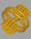
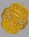
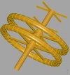
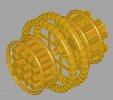
Taking a different tack, this time with a smaller station - freeside. This is a modular station, originally a LFC repair depot taken over in a sort of management buyout after the LFC collapsed when its wholly owned homeworld was taken by the Outworld Federation in the last major action of the First Secession War.

It's a modular station, a variant of a type widely used. It can be constructed largely by hauling modules insystem and assembling them in situ.

This is still WIP, but I've been exploring arrays (polarArray in particular) to replicate copies of objects and this is so, so much faster to render than my first prototype.

Freeside1.jpg

Python:
# === Freeside.py ===================================

from math import sin, cos, radians, pi, sqrt
import cadquery as cq

def HabitatLink (wp, angle):
    radius = 350000
    height1 = 500
    height2 = 1000
    dock_rad1 = 15000
    dock_rad2 = 15500
    link_width = 1500

    c1 = wp.workplane(offset=height1/2).\
        cylinder(height1, dock_rad1)
    c2 = c1.faces('+Z').workplane(offset=height2-height1).\
        cylinder(height2 - height1, dock_rad2)
    c1 = c1.union (c2)
    #for th in range (0, 360, 10):
    #    theta = radians (th)
    #    (xx, yy) = (sin(theta) * dock_rad2, cos(theta) * dock_rad2)
    #    (nx, ny) = (-cos(theta), sin(theta))
    #    p1 = wp.transformed (offset = cq.Vector(xx, yy, 0),
    #                         rotate = cq.Vector(0, 0, -th)).\
    #        rect (link_width, link_width/2).extrude (height2)
    #    c1.add (p1)

    return cq.Workplane('XZ').union(c1)


# === Generates a habitat ring ========================
def HabitatSection(basep, angle):
    ou = 30000
    st = 10000
    cp = 30000
    radius = 350000
    
    rads = radians (angle/-2)
    xo = radius * sin(rads)# - radius * sin (0)
    yo = radius * cos(rads) - radius   

    wp = basep.transformed (offset = cq.Vector(0, yo,xo),
                            rotate = cq.Vector(angle/-2, 0, 0))

    sp = \
        wp.moveTo(0, ou).lineTo(st, ou).\
        spline([(ou, st)], [(cp, 0), (0, -cp)],
               includeCurrent=True).\
        lineTo (ou, -st)

    sp = \
        sp.spline ([(st, -ou)], [(0, -cp), (-cp, 0)],
                includeCurrent=True).\
        lineTo (-st, -ou)

    sp = \
        sp.spline ([(-ou, -st)], [(-cp, 0), (0, cp)],
                includeCurrent=True).\
        lineTo (-ou, st)

    sp = \
        sp.spline ([(-st, ou)], [(0, cp), (cp, 0)],
                includeCurrent=True).close()

    sw = sp.revolve(angleDegrees = angle,
                    axisStart= (-100, -radius),
                    axisEnd = (100, -radius))
    
    f1 = basep.transformed (offset = cq.Vector(0, yo,xo),
                            rotate = cq.Vector(angle/-2 + 180, 0, 0))

    f2 = basep.transformed (offset = cq.Vector(0, yo,-xo),
                            rotate = cq.Vector(angle/2, 0, 0))

    link1 = HabitatLink(f1, 10)
    link2 = HabitatLink(f2, 10)
    
    sw = sw.union(link1).union(link2)
    
    return sw


def HabitatRing(wp, angle, count, radius):
    hs = HabitatSection(wp.transformed(rotate= cq.Vector(0,90,0)), 10)
    hs2 = wp.polarArray(radius, 0, 360, 36).\
        eachpoint(lambda loc: hs.val().moved(loc))
    show_object(hs2)

def HabitatArm(wp, inner, outer):
    box_width = 30000
    box_height = 20000
    hp = wp.transformed (offset = cq.Vector(0, 0, 0))
    ha = hp.box(box_width, outer-inner, box_height,
                centered= (True, False, True))
    return ha

def HabitatArms(wp, inner, outer):
    ha = HabitatArm (wp, inner, outer)
    ha2 = wp.polarArray(inner, 0, 360, 4).\
        eachpoint(lambda loc: ha.val().moved(loc))
    show_object(ha2)
    
def HabitatHub(wp, inner):
    outer1 = 40000
    width1 = 90000
    outer2 = 50000
    width2 = 60000
    
    hp1 = wp.cylinder(width1, outer1)
    hp2 = wp.cylinder(width2, outer2)
    hp3 = wp.cylinder(width1, inner)
    hh = hp1.union(hp2).cut(hp3)
    show_object(hh)

def MainShaft(wp, outer, inner, length):
    s1 = wp.cylinder(length, outer)
    s2 = wp.cylinder(length, inner)
    s3 = s1.cut(s2)
    show_object(s3)


def StructuralArm(wp, radius, inner):
    root_width = 50000
    root_radius = 40000
    shear = 50000
    
    ap = wp.transformed(rotate=cq.Vector(-90,0,0),
                        offset=cq.Vector(0,0,0))
    
    b1 = ap.box (10000, 20000,radius,
                 centered= (True, True, False))
    
    b2 = wp.polarArray(inner, 0, 360, 4).\
        eachpoint(lambda loc: b1.val().moved(loc))
    show_object(b2)


p = cq.Workplane('XY')
hab_dist=75000
fac_dist1 = 180000
fac_dist2 = 380000

h1 = p.transformed (offset=cq.Vector(0 ,0, -hab_dist))
h1a = p.transformed (offset=cq.Vector(0 ,0, -hab_dist/2))

h2 = p.transformed (offset=cq.Vector(0, 0, hab_dist),
                    rotate=cq.Vector(0,0,180))
h2a = p.transformed (offset=cq.Vector(0, 0, hab_dist/2),
                    rotate=cq.Vector(0,0,180))

MainShaft(p, 30000, 28000, 800000)

HabitatHub(h1, 28000)
HabitatRing(h1a, 10, 36, 360000)
HabitatArms(h1a, 30000, 340000)
HabitatHub(h2, 28000)
HabitatRing(h2a, 10, 36, 360000)
HabitatArms(h2a, 30000, 340000)

h1b = p.transformed (offset=cq.Vector(0 ,0, fac_dist1/2))
h1c = p.transformed (offset=cq.Vector(0 ,0, fac_dist2/2))
StructuralArm(h1b, 200000, 29000)
StructuralArm(h1c, 200000, 29000)


#HabitatRing2(p, 10, 36, 360000)
#HabitatRing1(p, 10, 36, 360000)

#dp = HabitatLink(p, 10)
#show_object(dp)


#sp = HabitatSection(p, 10)
#show_object(sp)
 
Nice :smile:

I'm trying to learn how to use Blender as well, and while I made a model of the ship the group are using in Traveller and 3D printed it, I haven't even begun looking at scripting to generate stuff. I really like the results you have got out of it.

A question, why did you use CADQuery instead of the built in Python interpreter in Blender? As I've never looked into it myself, I don't really know the capability of the Python API in Blender, or how hard it is to do stuff with it, I just know there is (or at least was) one.

CADQuery was designed for this so the API is fairly straightforward, although I'm finding the documentation and availability of examples a bit patchy. It's a wrapper around a geometry engine called OpenCascade. I may still go back to Blender for this as its support with 3rd party examples is much better.
 
CADQuery was designed for this so the API is fairly straightforward, although I'm finding the documentation and availability of examples a bit patchy. It's a wrapper around a geometry engine called OpenCascade. I may still go back to Blender for this as its support with 3rd party examples is much better.
Looks like I should look into both, when I get around to it :smile:
 
Freeside Station, another wretched hive of scum and villainy. Judicious use of polararrays and stacks on the workplanes means this renders much, much faster. In-game, this is an old LFC modular station in a repair depot configuration now taken over by smegs and a place to get repairs done no questions asked. The habitat rings are about 700m across with a girth of around 70m..


Freeside2.jpg
 
Banner: The best cosmic horror & Cthulhu Mythos @ DriveThruRPG.com
Back
Top